
Structural SHIPtember: Perfecting Polygons for Frame and Glory
/Today’s guest article comes from Huib Versteeg, an engineer and veteran LEGO SHIP builder with lots of experience on how to build both sturdy and complicated SHIP frames.
Introduction
Greetings SHIPwrights! As you may have heard through the grapevine, or simply noticed by looking at the calendar, SHIPtember is fast approaching. If you’re unfamiliar with the concept, I would direct you to this great article featured previously on BrickNerd where Oscar gives a nice overview of what to expect and how to participate in this fantastically fun annual event. Essentially, SHIPtember is a one-month challenge to build a LEGO spaceship at least 100 studs long, hence the “Seriously Huge Investment in Parts.”
Here, I will be focusing on one very specific part of building a SHIP: structural integrity. This will be quite a deep dive with one simple goal: to give you the tools you need to build a beautiful SHIP that is also rigid enough to be both swooshable and displayable on a single-legged stand.


But who am I to tell you all this? I love building spaceships and other sci-fi vehicles, and first took part in SHIPtember in 2014. I’ve participated four times (running out of time once) and have really come to enjoy the community and building challenge aspects of it. I also have a background in mechanical engineering and a love for recreational mathematics, both of which I tend to apply to my LEGO creations. This can be either for incorporating functions/mechanisms or enhancing structural/geometry aspects, the latter of which we’ll be looking at today.


I would also like to clearly state up front that this is not meant to discourage building anything that might not meet suggestions made here. You might be looking to create a very specific aesthetic that just wouldn’t work well without extra support, or you might simply think this is not an important aspect for your build. Whatever SHIP you decide to create, though, I hope you will find something useful in this article!


Some spaceship concepts do really need extra support in Earth gravity.
First Principles
The first thing you’ll want to consider is the direction in which your SHIP will be the longest. For static display, a vertical build may need much less reinforcement, as most loads are either pure compression (parts pushed together, bottom stand) or pure tension (parts pulled apart, hanging mount). Compression we could even handle with just a purely studs-up approach, while pure tension requires some sideways construction (though it is generally still simple to deal with).


Vertical SHIP examples.
However, things change dramatically when we want to build the most popular kind of SHIP: a horizontal one. This introduces large bending loads, which will try to pry apart your carefully placed bricks in all manner of unfortunate ways.


For our SHIP to be structurally sound, we will have to make sure that all the bricks stay together (strength) and that we get little deformation when we start adding weight (stiffness). To this end, we’ll look at what bending does to a stack of bricks and how we can most efficiently counteract these effects.
For the sake of practicality, I won’t go into detail on why certain effects happen, though you can peruse some background material here if desired. The largest internal forces/stresses we’ll have to contend with are tension at the top and compression at the bottom of the frame/beam. Next to this, there will also be sliding forces along the horizontal plane. Lastly, if left loose, the ends of bricks on the top and the middle of bricks on the bottom will also work themselves loose. These effects are illustrated in an exaggerated manner below.

1) Top tension, bottom compression; 2) Horizontal sliding; 3) Bricks separating at ends/middle.
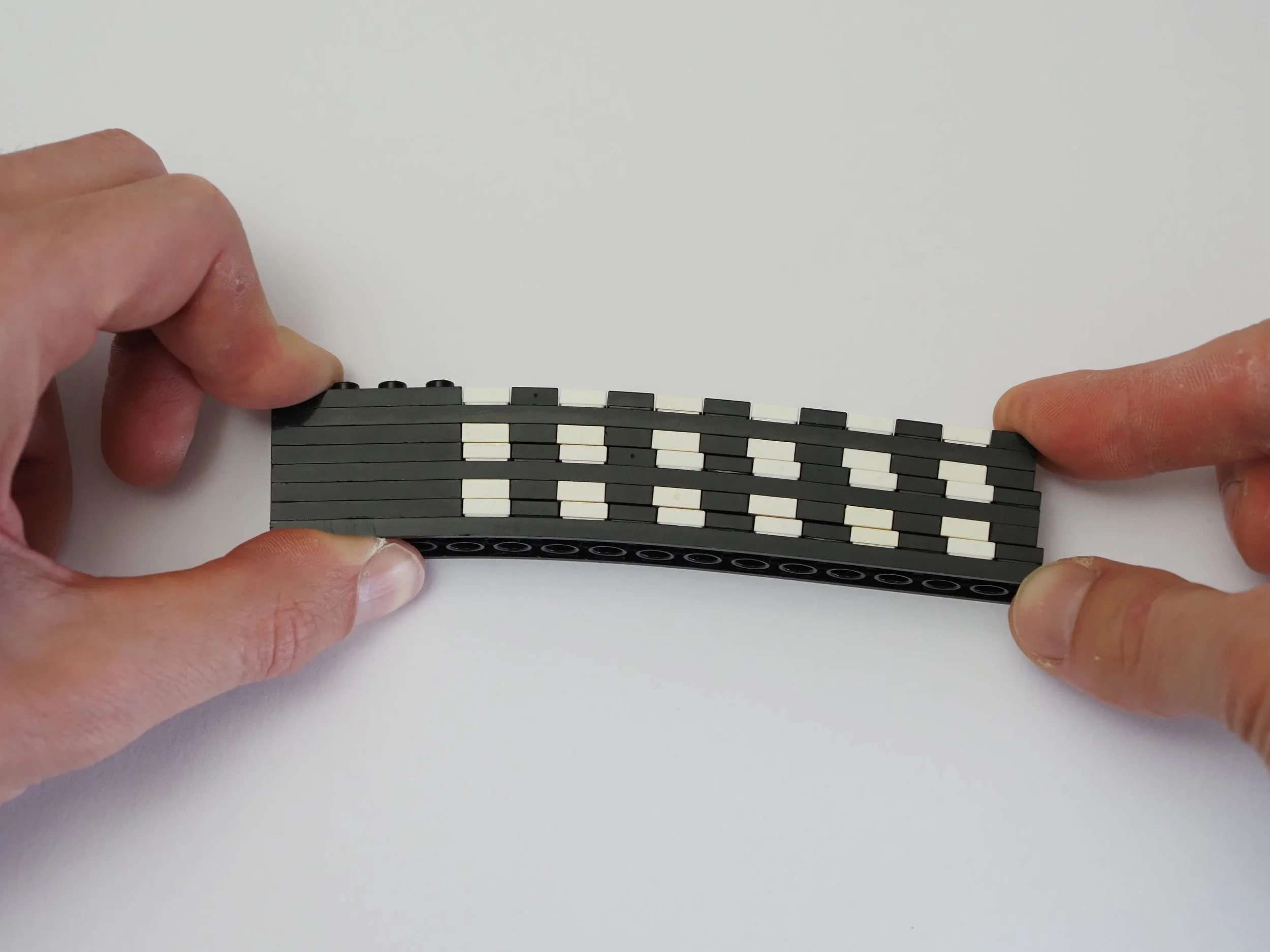
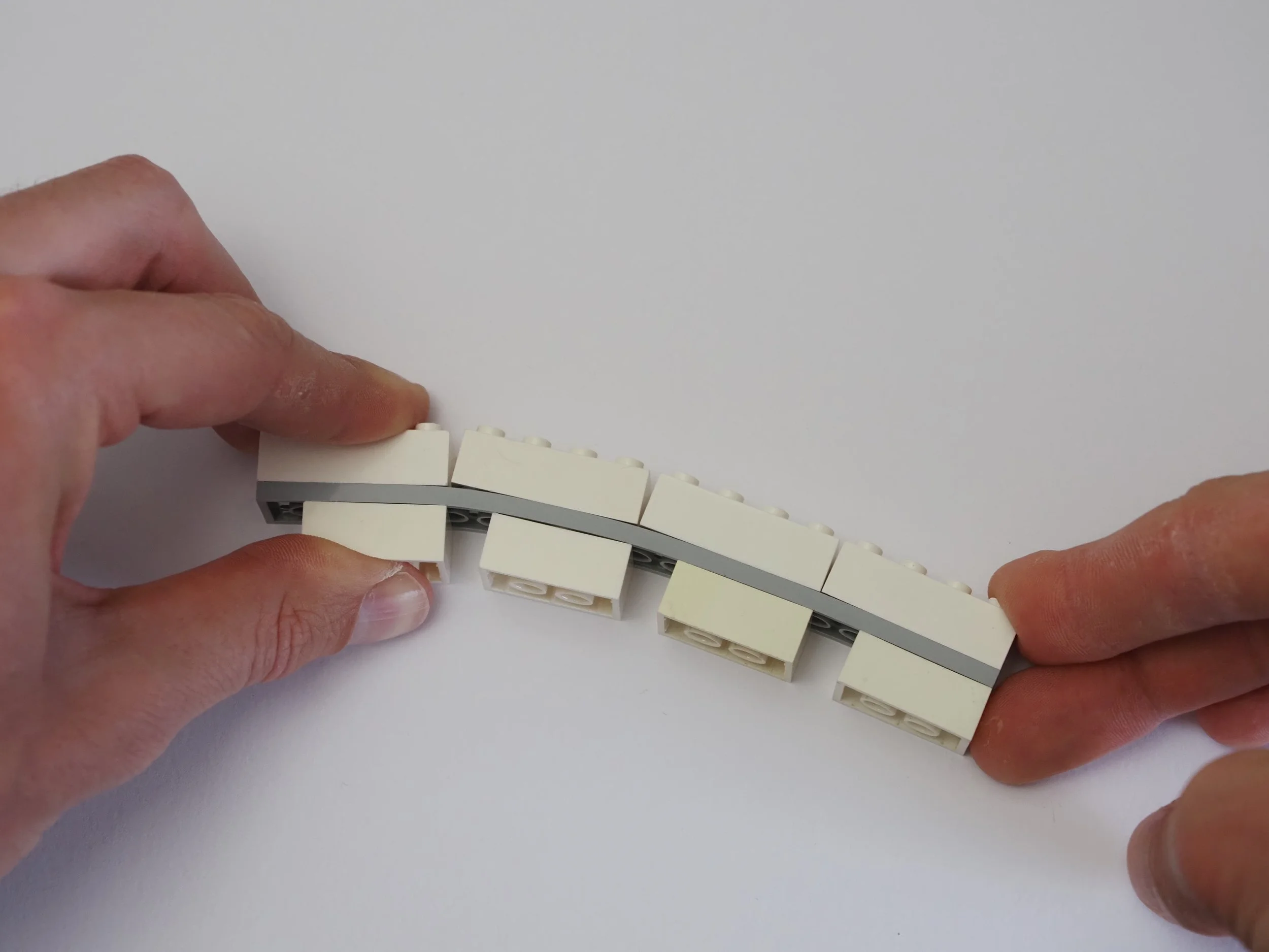
Because we also have to deal with tension now, we can no longer just rely on bricks pushing into each other for stability. Standard stud connections are much easier to pull apart (possible for any child, just friction) than to slide apart (you’ll sooner break the bricks, shape-locked). This is why we want to have all loads primarily supported by sliding stud connections. It just so happens that this is possible for all the forces arising from bending if we build our primary structure sideways.
The math and physics also work out so that we can address stiffness in the same step. Doubling the height of a beam increases its stiffness by a factor of 8, whereas doubling the width only doubles the stiffness (a fact that is easy to check for yourself by trying to bend a 2x plate sideways or vertically). The most effective piece here should thus be thin and tall: a wide sideways plate! Other wide and thin elements also work well, such as 30489, 69958, 65803, and 30400, among others.


Now, even though this takes care of our primary loads, the “frame” is still very floppy sideways and easy to twist lengthwise (see above). For the same reason that adding height was disproportionately effective earlier, a neat way to address this is by adding more material as far away from the center of the frame as possible (there's a reason I-beams and hollow tubes are used extensively in actual construction).
An example frame I’ve created similar to this can be seen below. At 96 studs in length, it can easily support an 8kg tub of bricks without breaking a sweat (I’d say that’s plenty for any SHIP that size). For a more extreme example, I would point you to the LEGO Masters US Season 1 bridge challenge.


Here we also first encounter SNOT brackets, which are used to add strong sliding connections in new directions, lock larger elements together, and to reverse stud directions. You may also notice this is very similar to the structure some SHIPs and other builds already use for their exterior (studs out on all sides). With this in mind, there is a lot to gain when integrating the exterior and frame in terms of weight and parts use (for instance, I did this two years ago with a Znap core). How this can work out in practice is highly dependent on the SHIP shape though, so I won’t go into it further.
This also brings us to the last important point I would like to make here, which is to carefully mind symmetry and locking loops in frame construction. Though it is possible to create asymmetric cross-section beams, this will result in extra twisting effects perpendicular to the section when bent, or bending loads when put under tension/compression. In all, this makes it harder to predict what loads will do when applied to a given structure and to make that structure strong and stiff.


Twist from asymmetric beam bending; Bending from asymmetric/offset tension/compression.
Maintaining symmetry when dealing with SNOT brackets often comes down to creating loops with plates on all sides around a structure that would otherwise be prone to self-disassembly. For me, this has proven to be a very useful and relatively simple way to think about this particular concept, even when first building digitally, for example.

Now, how big should all of these elements be? That depends entirely on the size and eventual weight (distribution) of your SHIP. The main advice I can give is to just try things out and see if you’re satisfied with the way your build handles itself when picked up and swooshed about.
Perhaps as a last rule of thumb for maintaining stiffness for any frame member, I would use general rule: “Double the length? Double the height!” Conversely, “Half the length? Half the height!” should also work.
Why Not Technic?
With all the above in mind, you may still wonder, “Why don’t you just use Technic? Isn’t this what it was made for?“
At its core, Technic is exceptionally well-suited for builds involving mechanisms, movement and geartrains, and allows for direction changes in very small spaces. It can also be used to make some great lightweight trusses and triangular structures.
There are some downsides, though, especially when relying on it for SHIP frame construction:
Pins introduce a small amount of wiggle room, which will add up over longer distances, and can get amplified depending on how a specific connection is made
It is difficult to create thicker/stiffer Technic beams out of base elements, without falling back on system brackets and plates. Elements such as 64782 can remedy this though, as seen in the internals of the most recent UCS Star Destroyer.
Proper locking and symmetric load loops can take more space than what would be needed with plates and brackets. (Side to side, studless Technic beams also have a bit of extra room, meaning you can’t truly lock them in place rigidly.)
And the final nail in the coffin for this particular application: (studded) Technic at various angles does not stay “in system”; the connection points no longer line up with regular SNOT pieces. In practice, this makes adding connections between the interior and exterior that much more difficult. (Not to mention the unfortunate 0.1 mm vertical offset in the location of Technic pin holes.)


Amplified pin wiggle room; Locked connection with large loop and beam wiggle room; Out-of-system sideways studs with studded Technic.
Technic can still be very useful for adding more interlocking parts in thin sections, as well as adding angled sections to the exterior (see, for instance, the internals of the UCS Razor Crest). If you want to add any kind of functionality or mechanism to your build, it is also still the way to go. However, unlike me from 10 years ago, I would not recommend it anymore for the structural backbone of a SHIP.


Some SHIP mechanisms of my own (landing gear, turret, engine pods), both with somewhat outdated frame constructions.
Adding 2D Angles
So far, we’ve only looked at rectangular box frames. If we want to spice things up a bit with angular elements, we’ll have to introduce hinges and fix them in place by arranging elements in triangles, possibly with the addition of some right angles.
For the most basic hinge, we can simply use studs themselves and rotate plates around these. This can get cumbersome quite quickly though, so luckily there is also a plethora of parts available for more compact and sometimes stronger connections. This ranges from hinge plates to Mixel joints, larger ball joints, rounded plates, click hinges, Technic and specialty angled parts.


There is actually a bit of math involved here, though in practice it usually boils down to bookkeeping/addition. As a starter, I would point you to the excellent series of articles “Escaping the Grid” by Arno Knobbe over on New Elementary or to BrickNerd’s own articles on LEGO Math by Deep Shen, both of which have something to offer for both new and experienced builders alike. I’ll briefly talk about some of the subjects mentioned there, while also expanding in certain directions, putting a little extra focus on structural integrity and adding some new interesting techniques into the mix.
The most well-known, but unfortunately also the most restrictive triangle option is one that has a Pythagorean triple as side lengths. This results in all three corners being “in system” which makes them easy to incorporate.

Unfortunately, there simply aren’t all that many of these triples with small enough numbers for them to work well in LEGO builds, which restricts the angles that can be achieved. We can get access to more by working with units smaller than a stud (½ studs, plates, half plates, and even quarter plates), as also discussed by Arno. I’ve found that the effort to also make things structurally sound in such a case is often large, so this ends up as quite a niche method.

Adam Cunningham and John Ringland, CC BY-SA 3.0, Via Wikimedia Commons
An option that opens up many more different angles is what’s come to be known as reflected triangles, and its subset reflected wedges (again two articles by Arno). Even at a small scale, there are quite a few options for these, and with hinge plates and Mixel joints, they allow for many connections and a structurally sound whole, as well as very subtle angles when used with parts that allow small offsets (see example below). As a result, they’ve also seen countless uses in LEGO sets of the past decade.


Reflected triangles; The special case where the reflected triangles are the same as certain wedges.
As an expansion on the above, it turns out there are quite a few right-angle triangles that share a non-integer hypotenuse with a different right-angle triangle. There are a few examples of these in LEGO sets, for instance in the Mos Eisley Cantina in steps 103 and 121, and in Rivendell in Book 3 step 94. A special case shows up in the Spider-Man Art set where both triangles are in a different plane, forming a 3D composite angle. For the latter, a longer explanation is given in the three images below.


Two occurrences of the same pair in Mos Eisley, with one of them flipped; Occurrence in Rivendell with explanation.


Occurrence in Spider-Man Art set with an explanation split over different steps. (Images from LEGO)
As far as I’m aware there is no existing math term for these, though LEGO has come to call them “Pythagorean pairs.” I myself might go for Gaussian integer pairs, as their existence is closely linked to prime factorization of Gaussian integers (a topic which you may immediately forget about again if you so desire). That might be just a little bit too much advanced math for the typical consumer, though…
For practical purposes, I’ve created a small overview of all the options up to a hypotenuse length of 25. This also includes Pythagorean triples within range (magenta squares) and some lines to indicate common wedge piece dimensions. Because the two triangles are different, each pair also gives two options for orientation, which can be seen in some example LEGO implementations below.


Some examples in LEGO form. Top and bottom use the same pair, but with one triangle mirrored along the hypotenuse.
So far we’ve also only looked at right-angle triangles. This is absolutely not a requirement, though, and extending our range to include any kind of integer side length triangle creates even more possibilities. This does mean that only two of the three corners will ever be in-system / on-grid for any given side, but this is not necessarily an issue.

Isosceles integer side length triangle and a generic integer side length one, with scaled versions for extra support.
For these, and any triangle-based angular construction for that matter, we can make a strong and stiff connection by starting with a relatively small triangle, and copying it/scaling it up several times (making use of shape similarity). Combining Mixels joints (or jumpers and regular plates) with hinge plates allows for even more connections in such a setup. The rotation centers for these parts are offset by ½ stud in one or two directions, allowing sturdy connections at half-stud lengths, as illustrated in various earlier examples.
Adding 3D Angles
Stepping into the third dimension is also possible with only some slight additions to the toolbox we already have.
Firstly, we can create an angle in one dimension, rotate our building direction, and create another angle. If we do this with Pythagorean triple pairs, we get two sides that are both in-system which we can also integrate even further with the use of ball joints, as these allow for 3D rotation. This can rapidly get quite math-heavy, so just be prepared.
I’ve constructed an example with (3, 4, 5) and (7, 24, 25) length triangles below, where the first can be measured in studs and the second in plates. I’ve only included a locking loop for the 7-plate length section, as that is somewhat more unusual due to the odd length. All other parts still require some reinforcement for practical SHIP use (left as an exercise for the reader).


Another interesting approach is to use two sets of reflected triangles at 90-degree angles. This provides many more options than Pythagorean triple pairs, but also results in a different kind of rotation, as the joint is symmetric rather than stacked. These should be easier to construct in reality (though they are almost impossible to set up digitally with Stud.io). They can also be set up to support reflected wedges on all sides for a special finish.
As a generalisation of this method, it is also possible to form any kind of reflected tetrahedron by foregoing the requirement of 90-degree angle between the two corner triangles. In both cases, the minimum number of corner joints is 3, though it is always possible to add more by extending the pattern. An example of the first option can be seen below.


Single sets of reflected triangles and Gaussian integer pairs can also be set up to give out of plane angles, as demonstrated by the Spider-Man Art set before. It, is of course, possible to use any other combination of triangle techniques to create the 3D orientation you desire.

Cmglee, Via Wikimedia Commons
There’s also Pythagorean quadruples, which are about as restrictive in 3D as Pythagorean triples in 2D. Hence, I’ll not go further into these here, though they may come in useful in certain niche cases.
Finally, if we forgo the requirement of integer leg lengths in all 3 dimensions, but we do want to keep an integer hypotenuse, we can extend the 90-degree reflected triangles/Gaussian integer pairs to get structures like the one in the recent Space Shuttle Carrier set. This simultaneously adds a bit of dihedral and a 45-degree sweep angle to the wings.
To get the top corner to have integer spacing in 2 out of 3 dimensions (indicated with red circles in the image below), one of the two triangles has to be scaled up by the ratio of its hypotenuse to one of its legs and rotated so that that leg now overlaps with the earlier hypotenuse.
Alternatively, this can be thought of as adding an extra scaled similar triangle to the original construction. In this case, we go from an original pair of (7, 1) (5, 5) to adjacent triangles with sides {7, 1, sqrt(50)} and {sqrt(50), sqrt(50), 10}. (You’ll be forgiven if you didn’t quite follow all that, it’s a somewhat niche case.)

Image from LEGO.com
Regular Polygons
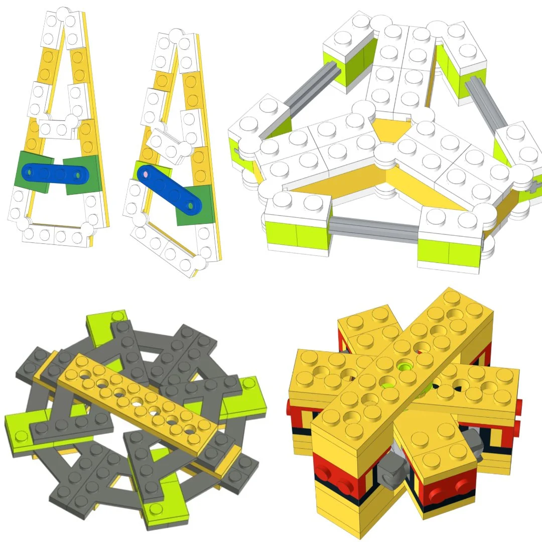
As a final set of tools, we’ll take a look at constructing some structurally sound regular polygons. These have a tendency to pop up in certain styles of SHIP, and there are some interesting techniques to explore with them.
Firstly, we’ll look into a combination of regular triangles and hexagons. These are closely linked in terms of geometry, as a regular hexagon can be constructed from six regular triangles. A hexagonal frame can also be turned into a triangular one by simply ignoring half the sides. This is also among the regular polygons where specialty pieces exist that already include the required angles, see below (the large Technic banana gears actually have 24 equally spaced attachment points, for even more possibilities).


As a triangle on its own is already a stable structure, in theory it should be relatively simple to construct a perfect regular triangle and hexagon. However, doing things this way leaves little room for a rectangular structural core, and few attachment points due to the way the math works out. Such a structure is not always necessary to include, but can be very useful if you don’t want your entire ship to be triangular/hexagonal in nature.


Perfect regular hexagons with plates; With dedicated Technic pieces; With plates, including combine harvester plate and rectangular central frame.


Exact regular triangle/triangular examples. The first does not have integer side lengths.
What we can do instead is approximate a regular hexagon with the power of truncated continued fractions. It’s not really necessary to know the math behind this, just that the square root of 3 (which pops up all over the place in regular triangles) can be decently approximated with an integer ratio of 7/8 (1% too big), or even better with 13/15 (0.07% too big).
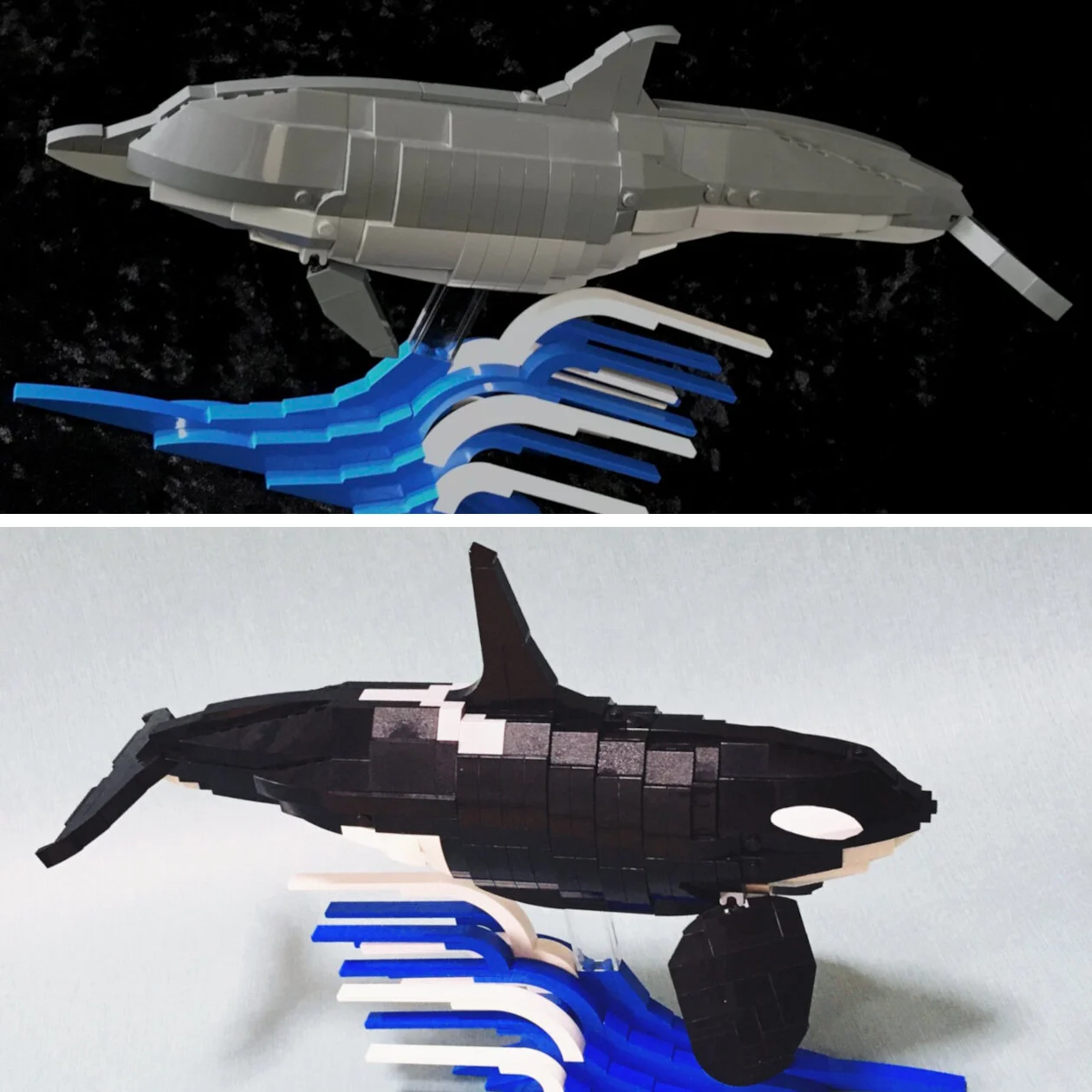
The first approximation I initially encountered in some of Julie-v’s creations, where she uses it as a simple way to create the distinct angular sections of ships from The Expanse TV show. The other approximation I first saw from Tim Gould.

First hexagon approximation, less accurate (1%)

Second hexagon approximation at three different scales, very accurate (0.07%).
Because one of the two numbers in the last ratio is a multiple of 5, it can also be scaled down all the way to half plates while maintaining integer stud lengths along the outside. The smallest version of this first showed up on my radar in the engine nacelles of Oscar’s SHIPtember build from last year, and is based on Mixel joints.

The second approximation is also so good (at small scale, it’s off by much less than the thickness of a hair) that it allows turning these approximations into actual regular polygons, at the cost of a little bit of (illegal?) stress on the bricks. There’s some SNOT shenanigans involved to get the right offsets, but the end results are very nice and stable, with plenty of connection room for other frame elements.


Perfect regular triangles/hexagons with slightly stressed pieces, and an example application.
Besides triangles and hexagons, we can also make perfect regular pentagons with LEGO. The first option here is to use one of two recently introduced parts: 80273 or 1936. As far as I know, these are the only 5-sided parts that LEGO makes. They allow for a center connection and prongs going out in the direction of the five vertices of a pentagon, but not an exact side length to put in between.
We can use another truncated continued fraction approximation here (thank you, Wolfram Alpha) to get very close with a ratio of 20/17 (~0.075% off). In the example below, this is measured in half plates though larger versions are of course also possible.

If we want to construct a rigid pentagon with integer side lengths ourselves, we will have to construct a beam with a length that is an integer multiple of the golden ratio, an irrational number. This is possible by using the hypotenuse of a right-angle triangle with other side lengths 1 and 2 (for the square root of 5), together with some regular (half) stud length pieces (for the remaining part of the golden ratio).
There’s some extra trickery involved as we need to keep both lengths aligned, which is handled by Technic axles/bricks in the larger examples and bars/SNOT bricks in the smallest example below.
There’s no (easy?) way to also get a stud connection at the exact center of a pentagon, though again, we can get very close with an approximation. The perpendicular center distance is very close to 11/16ths of the side length (~0.1% off). For a pentagon with side lengths of 8, this comes down to a very simple value of 5.5 studs which is indicated in the largest example above.
More Polygons
Lastly, I’d like to go over some regular polygons that show up less frequently, but may still be useful: octagons (8 sides) and dodecagons (12 sides).
Octagons can be constructed with click hinges, which can also be used to create hexadecagons (16 sides). These hinges have a slight amount of wiggle room, so they may not be the best choice for high loads. They can easily be pushed into coercion for more decorative elements though, like on this SHIP by BrickNerd’s Sean Mayo.

Random Vector by BrickNerd’s Sean Mayo
More recent additions that are suitable for octagon construction are two parts with a built-in 45-degree angle: 15706 and 79846. Here we can employ a similar hypotenuse trick as with the pentagon (or simply some symmetry if you prefer) to rigidly add a central core element, as shown in some examples below.

The last geometric structure I would like to point out is a way to create a regular dodecagon using regular triangles and squares. This method also leaves a regular hexagon in the center and can thus be used instead, or to complement a hexagonal core.

More-sided polygons start to go into the realm of circle approximations, which I’ll leave as a whole different topic (and which I’m also not well-versed in).
To conclude, this is only a small part of the techniques and methods you might (or might not) come across when attempting to build a SHIP, and very much errs on the technical side (less so the final aesthetics).
From brick bending to greebling, SNOT and all kinds of other machinations though, it can all come in handy. Whatever you may have learned from this article, I hope you’ll have fun with SHIPtember, and to see all your mighty fine spaceships at the end of the month!
Why haven’t you built a frog yet? What are you waiting for!? Let us know in the comments below.
Do you want to help BrickNerd continue publishing articles like this one? Become a top patron like Marc & Liz Puleo, Paige Mueller, Rob Klingberg from Brickstuff, John & Joshua Hanlon from Beyond the Brick, Megan Lum, Andy Price, Lukas Kurth from StoneWars, Wayne Tyler, Dan Church, and Roxanne Baxter to show your support, get early access, exclusive swag and more.


